

Power, efficiency and productivity for steel, timber, aluminium and concrete structures
CYPE 3D is an agile and efficient program brought about to carry out structural calculations in 3 dimensions of bars made up of steel, timber, aluminium, concrete or any other material, including the foundations with pad footings, piles and strap and tie beams. If the structure consists of timber, steel or aluminium bars, the program can redesign them and so obtain their maximum optimisation.
- General data
- Limit states. Loadcases, combinations and loads
- Node types
- Bar structure types in CYPE 3D
- Other properties of bars in CYPE 3D
- Shells in CYPE 3D
- Fire resistance check
- Welded and bolted connections
- Baseplates
- Baseplate dimensioning using the Joints I, Joints II, Joints III, Joints IV and Joints V module
- Baseplates designed with Baseplates module
- Baseplate design options
- Baseplate code check
- Foundations
- Help with data introduction
- Analysis using multiprocessors
- Results, drawings and reports
- Detailed ultimate limit state check reports
- Export to Tekla Structures
- CYPE 3D Modules
CYPE 3D has been developed to offer the user a software program with greater assistance in the design of steel, aluminium and timber structures (design of connections, ties, bracing, etc).
CYPE 3D can operate as an independent program and within CYPECAD as an integrated 3D structure.CYPE 3D analyses any type of structure made up of steel, aluminium or timber bars and carries out all the checks stated in the selected code. It has been adapted to the CTE and to other national and international codes for steel, timber, aluminium and concrete (foundations) structures. The program undertakes a fire resistance analysis, design and check on all timber sections. For steel sections, the fire resistance is checked and the protective coating is designed. Earthquake analysis is also carried out (Modal Spectral Analysis) in accordance with the national and international code. 2nd order effects (P-delta) are considered with wind and earthquake loadcases.
Consult our marketing department or your usual distributor of CYPE products for a list of the available national and international codes for this program and their corresponding prices.
Limit states, loadcases, combinations and loads
It is possible to configure different limit states for each material.
The program also allows to visualise and print a report with the project properties, with and without earthquake loading, in which the partial safety coefficients (load increment) and the combination coefficients ψ for each type of load (nature) are displayed.
Loadcases and Loadcase combination
 CYPE
3D automatically generates the self weight of the introduced bars, creating
a dead load loadcase. It is possible to add an infinite number of additional
loadcases of the same or of a different nature (dead load, live load,
wind, earthquake or snow).
CYPE
3D automatically generates the self weight of the introduced bars, creating
a dead load loadcase. It is possible to add an infinite number of additional
loadcases of the same or of a different nature (dead load, live load,
wind, earthquake or snow).

Simple loadcases and their combination (compatible, incompatible and simultaneous) can be defined by the user. The program automatically generates the combination of these loadcases according to the previously indicated conditions.
For example, the program automatically generates the loadcase combination corresponding to a load situation composed of a general live load and a load trolley acting at various positions. The positions of the trolley are incompatible with one another but each one of them is compatible with the general live load and any other loadcases of a different nature.
The generated combination of the loadcases of the same nature can be viewed. This way, it is possible for the user to check whether or not the conditions are correct.
 The
program allows for multiple load types such as, for example, point, line,
line with height variation, surface, surface with height variation, temperature
increment and gradient, moments etc. The loads can be introduced on nodes
and bars.
The
program allows for multiple load types such as, for example, point, line,
line with height variation, surface, surface with height variation, temperature
increment and gradient, moments etc. The loads can be introduced on nodes
and bars.
Surface loads are introduced on panels that have been geometrically defined by the user by means of a closed polygon. Loads can be applied on all the surface of the panel or on polygonal surfaces contained within the panel. The user also indicates the direction of the introduced one way spanning loads on the panel which should be parallel to one of the sides of the panel.
The distribution of all the loads applied on the panel is similar to that of simply supported elements and is carried out on the bars contained in the panel that are not parallel to the distribution direction. In the case of loads defined on the surface of the panel, the distribution will only affect those bars which are closest to the defined surface.
In the integrated 3D structures of CYPECAD it is also possible to define surface loads in the same way as in CYPE 3D.
It is possible to define prescribed displacements in the fixities and supports, and prescribed rotations in the fixities. These displacements and rotations will cause forces to arise on the bars, and so when they are defined their effects have to be assigned to a loadcase.
 The
node type selection is very complete. The internal fixities and exterior
restrictions of nodes can be defined. The exterior restrictions allow
for the nodes to be defined as pinned, fixed or partially fixed, elastic
support (springs), supports with free displacement in a plane or defined
direction, etc.
The
node type selection is very complete. The internal fixities and exterior
restrictions of nodes can be defined. The exterior restrictions allow
for the nodes to be defined as pinned, fixed or partially fixed, elastic
support (springs), supports with free displacement in a plane or defined
direction, etc.
Ties can be defined between nodes. These ties are used to indicate that two or more nodes have the same displacements for all the loadcases. This displacement match can be established in one, two or three directions in accordance with the X, Y and Z global axes. A reference number, applied to each group of nodes whose displacements are tied, is displayed on screen.
The user should take into account that for two or more nodes to have the same displacements, an element or construction arrangement should be present in the structure which will be able to materialise this displacement equality.
Ties cannot be assigned to nodes making up the edges of braced rectangles when the tied displacement has its projection on the plane of the braced rectangle.
Bar structure types in CYPE 3D
CYPE 3D allows users to introduce bars made of concrete, steel, composite steel and concrete, aluminium, timber or any other material.
The program designs the section and provides its optimum size for bars composed of steel, aluminium, timber or concrete (if they have been defined as column or beam-type structural elements).
Composite steel and concrete bars can be defined if they have been introduced as column-type structural elements and, even though they are not designed automatically, they are checked by the program with the properties that have been indicated by users.
As of the 2016.a version, users are required to define the structural function an element carries out in CYPE 3D. There are 4 different structural types available:
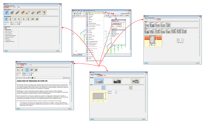
Generic-type structural elements
Elements defined this way do not have a specific structural role in the program. They can be defined as made of steel (rolled, welded or cold-formed), aluminium, timber, concrete or any other user-defined material (modulus of elasticity, Poisson’s ratio, coefficient of thermal expansion and unit weight).
The program designs the bars automatically if they have been defined as made of rolled, welded or cold-formed steel; aluminium or timber.
If they have been defined as reinforced concrete bars or bars made of a user-defined generic material, the program calculates the forces to which they are exposed and displays the results for each simple loadcase, combination or envelope; but their sections are neither checked nor designed. To check and design reinforced concrete bars in CYPE 3D, they must be defined as Column-type or Beam-type structural elements.
More information on these structural elements can be found on the Bars defined as generic-type structural elements webpage. 
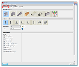
The element forms part of a bracing system and only works in tension. Transverse sections that can be assigned this type include flat bars, angles, solid round or square bars.
More information on these structural elements can be found on the Bars defined as tie-type structural elements webpage.
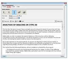
Column-type structural elements
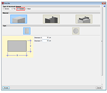
The element is a column and must be vertical. It accepts the following section definitions:
- Rectangular or circular reinforced concrete sections
More information on this module, used by both CYPE 3D and CYPECAD and used to design these structural elements, can be found on the Concrete columns webpage. - Steel sections
Can be rolled steel, cold-formed steel or welded steel. - Composite steel and concrete sections
More information on this module, used by both CYPE 3D and CYPECAD and used to design these structural elements, can be found on the Composite steel and concrete columns webpage.
More information on these structural elements can be found on the Bars defined as column-type structural elements webpage.
The element is a beam. It cannot be vertical and must not be rotated about its longitudinal axis. The sections that can be assigned are:
- Rectangular, L-section, T-section..., lattice or prestressed concrete beams
More information on this module, available for use with CYPE 3D and CYPECAD, can be found on the Concrete beams webpage. - Steel sections
Can be rolled steel, cold-formed steel or welded steel.
When an element is defined as a beam, the beam is composed of a single element. Nonetheless, the program allows users to define continuous beams composed of several beams.
More information on these structural elements can be found on the Bars defined as beam-type structural elements webpage.
Other properties of bars in CYPE 3D
CYPE 3D allows the user to introduce the ß buckling coefficients or the buckling length, the moment coefficient or the C1 coefficient of the lateral buckling critical moment formulation (if the selected code defines it) of each bar. Generally speaking, each code offers values for these coefficients associated to different bending moment distributions.
The program also automatically calculates the buckling length of the bars according to an approximate method, based on commonly accepted formulae, which requires for the user to classify the structure as a sway frame or a non-sway frame. The user can also activate the lateral buckling check for any bar.
The program allows the user to limit the deflection of the bars so that when designing the sections of the bars, it takes into account the imposed restriction (as well as the stress, slenderness, bucking, etc). The user may limit the maximum and relative deflection, for both its absolute and relative values for its length between ends and inflexion points of the deformed shape. The deflection may be defined as secant or tangent to one of the ends. It is also possible to define an element composed of various aligned bars for which the program checks its deflection as if it were a single bar. The dialogue boxes limiting the deflection of the bars have help captions available that define perfectly the different types of deflection the user may limit and the length to use as reference for the relative deflection.
Adjustments, displacements and rotations
When introducing bars, it is possible to carry out adjustments, displacements and rotations with respect to their introduction axis. The eccentricity produced by these adjustments and displacements is taken into account in the analysis, and so the program allows for the user to consider the true relative position between bars.
 Fixity
coefficients and rotational stiffness
Fixity
coefficients and rotational stiffness
The program alloys for xy and xz fixity coefficients or rotational stiffnesses in these planes at bar ends (bars or group of aligned bars forming an element). The option to define the rotational stiffness allows for joints to be modelled in which their stiffness to rotate is a fundamental consideration, as is in the case of bolted connections.
For each designed bolted connection, the program also analyses (for all the acting force combinations) the rotational stiffness of each element fixed to the connection and selects a rotational stiffness value for each element end, which will be that proposed by the user for the re-analysis of the structure.
Once the analysis has concluded, the program warns if the rotational stiffness introduced by the user for the elements fixed to the bolted connections differs in more than 20% to that proposed by the program or if it has not been defined.
CYPE 3D allows the user to automatically assign the rotational stiffnesses proposed by the program and check any he or she wishes to check to decide in which case which rotational stiffnesses are to be adopted.
More information can be found in the Rotational stiffness at element ends section in the Bolted joints page.
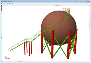
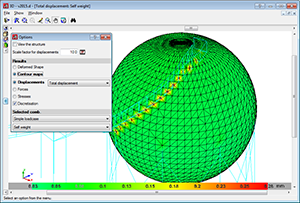
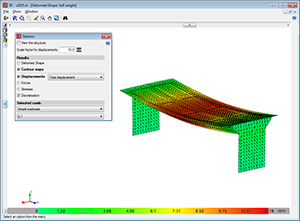
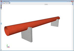
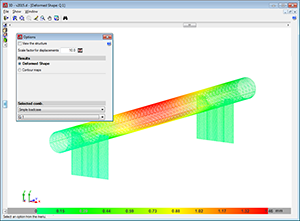
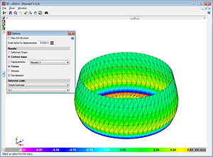
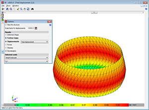
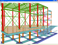
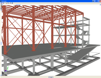
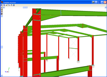
CYPE 3D allows users to define shells. Shells are flat two-dimensional elements with constant thickness and without openings, whose perimeter is defined by a polygon.
Shells are introduced in the global stiffness matrix of the structure using a three-dimensional finite element model composed of six-node (quadratic) triangular flat shells. The type of element used is based on the overlap of two locally decoupled elements: one provides the axial stiffness (membrane forces) and the other the bending stiffness (panel forces).
The following properties can be defined for each shell:
- Thickness and subgrade modulus
In the local Z axis direction - Material
Concrete, rolled steel, cold-formed steel, aluminium and generic material (by specifying the modulus of elasticity and Poisson’s ratio). - Position
With respect to the introduction plane - Discretisation
The density of the mesh can be controlled by defining the maximum size of the triangle in the local x and y axes. - Direction of the axes
- Internal fixity
Internal fixity between the edges and other elements of the structure. - External fixity
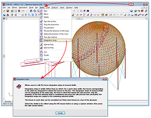
It is also possible to define the external fixity of the edges, but in this case, the fixity is applied to all the shells sharing that edge. The possible external fixity configurations are the same as those available for the nodes of CYPE 3D. - Integration strips
Integration strips in shells define lines on which, for a given strip width, the forces corresponding to the shell are integrated to obtain the bar forces.
To be able to use shells in CYPE 3D, users must have the permits required to use CYPE 3D.
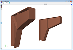
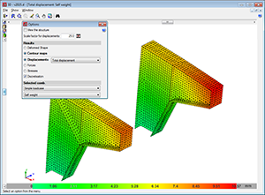
Below are some examples of structures created with shells in CYPE 3D:
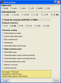
Using the new Fire resistance check module, CYPE 3D carries out a fire resistance check and designs the protective coating of the steel sections comprising the structure in accordance with the Eurocode (EN 1992-1-2:2004 and EN 1993-1-2:2005) and CTE code.
The fire resistance check for timber sections in CYPE 3D was already possible in previous versions and is carried out by a different module: the Timber sections module (common to CYPE 3D and Integrated 3D sections of CYPECAD). This module designs the timber sections for fire exposure so they comply with the selected design code (CTE DB SE-M –Spain-, NBR 7190 or Eurocode 5).
More information can be found on the Fire resistance check webpage.
The Joints modules designed by CYPE (Joints I. Welded. Warehouses with rolled and welded steel I sections, Joints II. Bolted. Warehouses with rolled and welded steel I sections, Joints III. Welded. Building frames with rolled and welded steel I sections, Joints IV. Bolted. Building frames with rolled and welded steel I sections, and Joints V. Flat trusses with hollow structural sections) can be used in CYPECAD and CYPE 3D (including the Integrated 3D structures of CYPECAD).
The type of joints resolved by the Joints I, Joints II and Joints V modules are more applicable to warehouses designed in CYPE 3D and the Integrated 3D structures of CYPECAD, whilst the joints designed by the Joints III and Joints IV modules are for more use in building structures composed of frames designed in CYPECAD. Nonetheless, each joint designed by any of the indicated modules is resolved in the same manner regardless of the program used, furthermore, the Joints I, Joints II, Joints III and Joints IV modules contain several types of joints common to both modules.
More information on the properties of these modules can be found at the following links:
Joints I. Welded. Warehouses with rolled and welded steel I sections
- Implemented design codes for welded joints
- Types of implemented welded connections
- Design options
- Welded connection design
- Joint consultation
- Baseplates designed using the Joints I module
- Joints report
- Joints drawings
Joints II. Bolted. Warehouses with rolled and welded steel I sections
- Implemented design codes for bolted joints
- Types of implemented bolted connections
- Design options
- Prestressed and non-prestressed bolted connections
- Bolted connection design
- Joint consultation
- Bolted joints report
- Bolted joints drawings
Joints III. Welded – Building frames with rolled and welded steel I sections
- Implemented codes for the design of building welded connections
- Implemented type of building welded connections
- Design options
- Design of building welded connections
- Consulting welded joints
- Baseplates designed using the Joints III module
- Joints report
- Joints drawings
Joints IV. Bolted. Building frames with rolled and welded steel I sections
- Implemented design codes for bolted joints
- Types of implemented building bolted connections
- Design options
- Prestressed and non-prestressed bolted connections
- Bolted connection design
- Design of building welded connections
- Joint consultation
- Baseplates designed using the Joints IV module
- Joints report
- Bolted joints drawings
Joints V. Flat trusses with hollow structural sections
- Implemented design codes for the design of flat trusses with hollow structural sections
- Types of implemented connections for flat trusses with hollow structural sections
- Joint design of flat trusses with hollow structural sections
- Joint consultation of flat trusses with hollow structural sections
CYPE 3D contains several modules which calculate and design baseplates: Joints I, Joints II, Joints III and Joints IV modules and the Baseplates module. The properties of the baseplates designed using the Joints modules and designed using the Baseplates modules are described below.
Baseplate dimensioning using the Joints I, Joints II, Joints III and Joints IV modules
The Joints I, Joints II, Joints III and Joints IV modules design welded baseplates with the following properties:
- Baseplate types: Welded baseplates for rolled and welded steel I sections sre designed.
- Welds: Includes the analysis and design of the welds between the plate, stiffeners, column and bolts.
- Automatic match: Automatically matches all the baseplates of a job (bearing in mind the section type, forces and exterior fixities). This way, and without the user having to intervene, the number of different types of baseplates is reduced, hence obtaining more uniform results.
- 3D View with highlighted elements and welds: It is possible to obtain a 3D view on screen whereby the baseplate, column, stiffeners, bolts, factory welds and insitu welds are displayed in different colours, in a similar manner as to how joints are represented between I sections. This has been incorporated to help the user understand how the support is to be assembled.
- Baseplate layout: A layout diagram of the baseplate is generated in which the details of the designed welds and stiffeners are displayed. This layout diagram can be included in the job drawings.
- Takeoff and code check reports: Takeoff and code check reports are generated of baseplates that have been resolved. These are integrated with the rest of joints that have been designed.
Baseplate dimensioning using the baseplates module
The baseplates module analyses and designs baseplates with the following properties:
- Basepate types: Resolves baseplates for any arrangement of steel columns (simple sections and composed).
- Welds: Does not include the analysis and design of the welds between the plate, stiffeners, column and bolts.
- Manual match: Baseplates may be matched manually by copying them over one another. Having copied it, the program carries out a code check of the assigned plate.
- Baseplate editing: The user can edit the baseplates, modify them manually and check the geometry of each plate, the bolt and stiffener layout, and the position of the column with respect to the plate (corner or centred at the edge) using the program.
- Baseplate layout and 3D view: The user can obtain a 3D view and a diagram of the layout of the baseplate on screen. The layout diagrams can also be generated in all the drawings of the job.
- Takeoff and code check reports: Takeoff and code check reports are generated of baseplates that have been resolved.
The baseplate design options are configured in the Options dialogue box (Baseplates > Options). The values established here affect the baseplate design of the modules that design them (Joints I, Joints II, Joints III, Joints IV and Baseplates), exept the type of bolt anchorage which only intervenes in the analysis carried out by the Baseplates module.
The Joints I, Joints II, Joints III, Joints IV and Baseplates modules carry out the following code checks (assuming rigid plate theory):
- On the supporting concrete:
- Compression stress: The compression stress on the baseplate-concrete interface must be less than the allowable stress of the concrete, which depends on the nature of each combination.
- On the bolts:
- The material resistance of the bolts: The forces acting on the plate are resolved into axial and shear forces in the bolts. It is ensured that both these forces when acting separately and interacting (Von Mises stress) produce stress smaller than the limit stress of the bolt material.
- Anchorage of the bolts: The anchorage of the bolts in the concrete is checked so that pullout, stripping, cone fracture or shear failure (crushing) does not occur.
- Crushing: The program checks that the shear that will cause the bolt to crush against the pat is not overcome.
- On the baseplate:
- The global stresses: In the case of baseplates with overhangs, four sections are analysed in the perimeter of the section and it is ensured that the Von mises stresses in each of them are less than the code limit stress.
- Relative global deflections: It is checked that for all overhanging sections of the baseplates, that the deflections do not exceed 1/250 of the overhang.
- Local stresses: The Von Mises stresses are checked in all the local plates in which the section as well as the stiffeners divide the plate. The forces in each of the subplates are obtained from the contact stresses with the concrete and the axial forces on the bolts. The generated model is solved by finite difference.
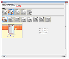
CYPE 3D analyses and designs footings and pile caps. Both foundation elements can be isolated or combined, i.e. they may support any number of columns.
Footings can be made up of reinforced or mass concrete, with constant or variable depth. The program can design them to be square, rectangular, eccentric, corner or edge centred. The analysis and design of the footings forms part of a module of CYPE 3D.
Pile caps allow for several piles. A wide range of types are available. They may hold 1, 2, 3 and 4 piles; linear and rectangular pile caps for any number of piles (from 3 to 30 per side); pentagonal pile caps for 5 and 6 piles, and hexagonal for 6 and 7 piles. The analysis and design of the pile caps is part of a module of CYPE 3D. For
use with footings and pile caps are strap and tie beams.
The analysis and design of the strap and tie beams are included in the
footings and pile caps module.
For
use with footings and pile caps are strap and tie beams.
The analysis and design of the strap and tie beams are included in the
footings and pile caps module.
The program offers the option of choosing the type of balancing of the ends of the strap beams by selecting the bearing pressure distribution acting below the footing in response to the soil, in order to calculate the forces on the strap beam and the pressures of the soil.
- Rectangular pressure distribution below the footing:
If this option is selected, the balancing of the beam is perfect, hence obtaining a rectangular pressure distribution in the soil.

- Trapezoidal pressure distribution below the footing:
The balancing of the beam is not perfect, i.e., a certain amount of rotation of the footing occurs resulting in a trapezoidal pressure distribution and therefore a reduction of the forces acting on the beam. If there is a trapezoidal pressure distribution below the footing, its resultant is displaced towards the column, which produces, approximately, a 10% moment reduction on the beam.
When a new job is created in CYPE 3D, an assistant is displayed to help the user introduce the general data of the job:
- Codes (Concrete for foundations, Rolled and welded steel, Cold-formed steel, Timber and Extruded aluminium) and activation of the seismic code (spectral dynamic analysis).
- Additional loadcases
- Limit states (load combinations)
- Steel data (rolled or welded and cold-formed)
- Timber data
- Extruded aluminium data
- Foundation data
The data of the material introduced in the assistant is the default data that will be assigned to each element that is introduced. Using the option Bar > Describe material, a material other than the default material can be assigned to any bar.
All the data introduced in the assistant can be modified once the assistant has closed. These changes can be carried out in the Job menu within the Structure tab and in the menu Job > General data of the Foundation tab. The Extruded aluminium sections option has been added to the Job menu so the default data for this material can be modified.
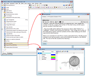
CYPE 3D allows for structural analysis models to be imported by means of an IFC file. IFC files only containing the physical model and not the structural analysis model, do not contain any information CYPE 3D can read.
In IFC files, the structural analysis model is composed of structural type entities, such as nodes, bars, loads, etc. The connection relationship between the nodes and bars is also defined using fixity conditions. It is similar to what a user defines in CYPE 3D.
The entities CYPE 3D imports from the IFC files are the following:
- Nodes (IFCStructuralPointConnection), with their external fixity conditions
- Bars (IFCStructuralCurveMember), with their end fixity conditions and their descriptions.
Introduction of the bars of the structure
CYPE 3D imports files generated in CAD programs with DWG and DXF format containing two and three dimensional data. Using these files, the geometry of the structure can be generated automatically (including selecting those elements to be imported classified by layer, entity, colour or linetype).
It is also possible to import DXF and DWG drawing files to use as templates. This way, the user can introduce the nodes and bars of the structure by snapping to the entities and elements of these files in the 2D windows of the program. The import process and use methodology of the DXF and DWG files is the same as in CYPECAD. The user has three buttons available in the tool bar which allow for these files to be managed:
 Imports the DXF or DWG, and allows for its layers to be managed.
 Activates or deactivated the view of the imported DXF or DWG in the active window.
 Manages the object snap settings for snapping to entities and elements of the DXF or DWG visualised in the 2D windows of the job.
Other tools are also available to facilitate data introduction: Zoom, Redraw, Orthogonal, undo, Redo, Repeat last element selection, etc. Object snaps can be used (end, mid point, perpendicular, nearest and intersection) as well as tracking (extend, perpendicular, orthogonal) on elements of the structure.
Using the view generation, it is possible to work with windows in 2D and 3D in a completely interactive manner and with complete connectivity. Additionally, in the 3D view, the visualised 2D plane is marked on screen.
CYPE 3D also provides the user with the option to automatically generate elements, such as nodes, bars and spatial meshes made up of tetrahedrons. It is also capable of creating an unlimited number of parallel frames based on one.
The elements are dimensioned without having to introduce coordinates or rigid meshes. When a node or bar is introduced, the program assigns a set of coordinates to it which depend on the position of the cursor on the snapped reference line or lines. After this, the user can dimension the nodes or leave the assigned coordinates.
Analysis using multiprocessors
CYPECAD and CYPE 3D offer the use of multiprocessors during their analysis.
To acquire these tools, CYPECAD and CYPE 3D have two new common modules which allow for substantial periods of time to be saved during the analysis:
- Parallel analysis with two processors
- Parallel analysis with up to eight processors
More information on these modules and a comparative study displaying the analysis duration with and without their use can be found in the Analysis using multiprocessors page.
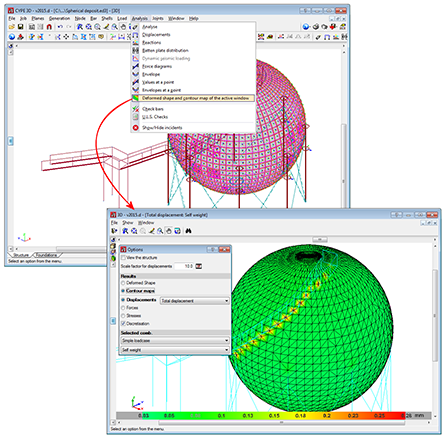
The force and displacement diagrams and envelopes can be consulted graphically or analytically on screen.
The bar check tool on screen, (stress, denting, buckling, deflection…) allows for a manual or automatic correction to be undertaken to obtain its final dimension.
Provides the drawings of any view of the structure, with all the required information, including elevations with the real dimensions of the section. The drawings can be exported in DXF and DWG format or printed using a printer or plotter.
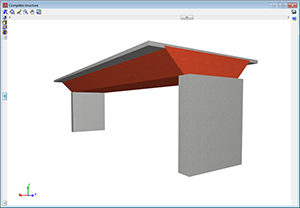
Generates 3D views with conical or isometric projection displaying the sections with their real size. These 3D views can be printed and exported in DXF, DWG, EMF, BMP and JPG formats.These 3D views can be printed and exported in DXF, DWG, EMF, BMP and JPG formats. The elements with textures resembling the real colours of their materials can be displayed. The user can represent the 3D view with or without the materials:
- Without materials. Displays the colours which differentiate the elements of the 3D view even if it consists of the same material.
- With materials. Displays the elements of the 3D view with textures resembling their real colour.
Free movement within the structure is permitted with conical perspective.
Provides node, bar and load data reports: reports containing results on the displacements, reactions, forces, stresses, deflections, footings, baseplates, etc of the structure. The takeoff report is also included. These reports can be exported in TXT, HTML, PDF and RTF formats. A preliminary view of these reports can also be obtained.
Detailed ultimate limit state check reports
CYPECAD, CYPE 3D and the Integrated 3D structures of CYPECAD generate detailed reports on the ultimate limit state checks of steel and aluminium sections.
These reports contain all the checks carried out by the program to design the structures and constitute an important document with which the user can:
- Verify the design of the sections
- Optimise the design of the sections
The level of detail of these reports also acts as a detailed guide so the user can know all the checks the section is submitted to.
Consult more information on the Detailed ultimate limit state check reports.
CYPECAD, the Integrated 3D structures of CYPECAD and CYPE 3D can export the analysed and designed structure to Tekla Structures.

More information on the export options can be found at Export to Tekla Structures.
CYPE 3D modules:
Modules common to CYPECAD and CYPE 3D:
- Concrete columns
- Composite steel and concrete columns
- Concrete beams
- Timber sections
- Pile caps (includes strap and tie beams)
- Baseplates
- Footings (pad and strip) (includes strap and tie beams)
- Advanced design of surface foundations
- Fire resistance check
- Parallel analysis with two multiprocessors
- Parallel analysis with up to eight processors
- Joints I. Welded. Warehouses with rolled and welded steel I sections
- Joints II. Bolted. Warehouses with rolled and welded steel I sections
- Joints III. Welded. Building frames with rolled and welded steel I sections
- Joints IV. Bolted. Building frames with rolled and welded steel I sections
- Joints V. Flat trusses with hollow structural sections
- Export to Tekla
There are two reduced versions of CYPE 3D:
CYPE 3D limited to 2 dimensions: CYPE 3D version limited to a two dimensional analysis. The same optional modules are available as those for CYPE 3D.
CYPE 3D student version: CYPE 3D version limited to 50 nodes and 50 bars. It does not include section design or any of the CYPE 3D modules.
Tel. USA (+1) 202 569 8902 // UK (+44) 20 3608 1448 // Spain (+34) 965 922 550 - Fax (+34) 965 124 950