
Bars defined as column-type structural elements
CYPE 3D is an agile and efficient program brought about to carry out structural calculations in three dimensions of bars made of concrete, steel, composite steel and concrete, aluminium, timber or any other material; shells (two-dimensional elements with a constant thickness whose perimeter is defined by a polygon). It includes the design of joints (welded and bolted rolled and welded steel I -sections and hollow sections) and of foundations (pad footings, pile caps and baseplates).
This webpage explains bars defined as column-type structural elements.
For information on other properties of CYPE 3D, visit the CYPE 3D webpage.
Bar structure types in CYPE 3D
CYPE 3D allows users to introduce bars made of concrete, steel, composite steel and concrete, aluminium, timber or any other material.
The program designs the section and provides its optimum size for bars composed of steel, aluminium, timber or concrete (if they have been defined as column or beam-type structural elements).
Composite steel and concrete bars can be defined if they have been introduced as column-type structural elements and, even though they are not designed automatically, they are checked by the program with the properties that have been indicated by users.
As of the 2016.a version, users are required to define the structural function an element carries out in CYPE 3D. There are 4 different structural types available: Generic-type structural elements, Tie-type structural elements, Column-type structural elements and Beam-type structural elements.
This webpage describes bars defined as column-type structural elements. To consult the properties of bars defined as other types of structural elements, please consult the following links: Generic-type structural elements, Tie-type structural elements and Beam-type structural elements.
Column-type structural elements
Levels and grids must be defined in CYPE 3D when bars defined as Column-type structural elements are introduced. A Column-type structural element can be assigned the following materials: Reinforced concrete (rectangular and circular concrete sections), Steel (rolled, welded or cold-formed) and composite steel and concrete sections.
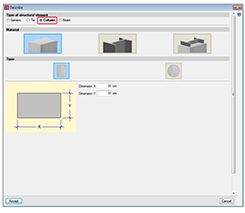
- Rectangular or circular reinforced concrete sections
To be able to define reinforced concrete bars as Column-type structural elements, users must have the “Concrete columns” module included in their user license. More information on this module, used by both CYPE 3D and CYPECAD and used to design these structural elements, can be found on the Concrete columns webpage. - Steel sections
Can be rolled steel, cold-formed steel or welded steel sections and are designed the same way as generic-type steel bars; although when they are defined as “Column-type structural elements” they are edited and modified using the “Advanced column editor”. Users do not require any special permits to be able to design columns with steel sections; users only require the license to use “CYPE 3D”. - Composite steel and concrete sections
To be able to define composite steel and concrete bars as Column-type structural elements must have the “Composite steel and concrete columns” module included in their user license. More information on this module, used by both CYPE 3D and CYPECAD and used to design these structural elements, can be found on the Composite steel and concrete columns webpage.
Column-type structural elements are designed, edited and checked using the Advanced column editor for the design codes implemented in the editor. Usually derogated codes or codes no longer in use are not available for use with the editor.
Properties of column-type structural elements
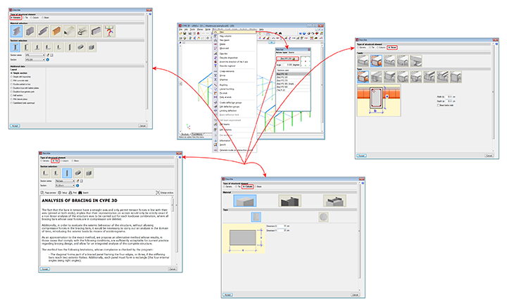
Columns are composed of elements whose structural type has been defined as being a column. A column can be composed of one or more elements. The column elements making up the column are vertical and have the same level parameters. Columns can be created in 3 ways:
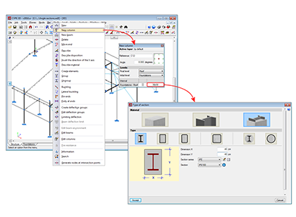
- By introducing a bar using the “New bar” option and selecting a column-type structural element description (Bar > New – see previous image).
- By assigning a column-type structural element to a previously introduced element (Bar > Describe).
- Using the “New column” option of the Bar menu (see image in this section).
Regardless of how they are created, the program will manage the composition/decomposition of the previously introduced columns. It is recommended columns be created using option 3. The “New column option” allows users to create a column between a range of indicated levels with the reference and sections defined by users by clicking with the mouse button at the position where the column is to be introduced.
The element must be vertical and be defined as being between two different levels. The element must be divided into bars, however, in the case of concrete columns, the reinforcement will be continuous along its complete length.
Once a group of elements has been defined as being a single column, CYPE 3D ensures the level parameters are the same for all of them. The level parameters of the column are defined using the “Describe disposition” option in the “Bar” menu.
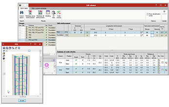
The remaining specific editing option for columns are located in the “Edit columns” option in the “Bar” menu. This option displays a toolbar containing the possible edit options. These options are:
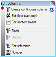
- Create continuous column
Creates a single column from a group of aligned elements - Edit floor slab depth
Allows users to edit the depth of the floor slab at a column node if they wish to assign a different value to that assigned automatically. The depth of the floor slab determines the free height of the column between levels. - Edit reinforcement
Allows users to edit column reinforcement by opening the column schedule. - Block
Blocks the reinforcement of a column so it is not modified during the design process. - Unblock
Unblocks any blocked reinforcement. - Edit reference
Edits the column references. - Number
Allows users to number consecutively all the columns of the job as of an initial reference.
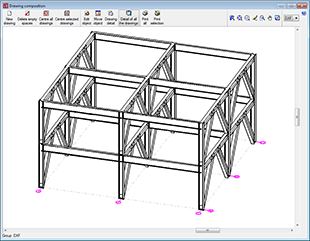
The program generates a solid model of the column taking into account floor slab depths at the nodes of the elements it is composed of. CYPE 3D automatically analyses these floor slab depths based on the elements reaching the nodes to established the real size of the column as well as the free height of the spans it is composed of.
Included in the “Planes” menu are the Levels and Grids options. These options are essential when introducing, revising and viewing jobs with Column and Beam-type structural elements:
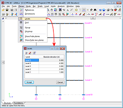
- Levels
Levels are horizontal planes parallel to the XY global plane, situated at a given global elevation where users can introduce a spatial sub-division as is the case in structural buildings. Assignment of the elements to the different levels is automatic. Elements situated between two levels are assigned to the closest lower level.
Levels are defined to support the introduction of structural elements as well as to define views of a level (which help when working on the elements of the structure). If columns are introduced, levels must be defined. Columns must begin and end at two different levels (although they may do so with there being an elevation change with respect to the two levels).
With this option, users can introduce, edit or delete levels. If the elevation of a level is modified, any elements contained in that level will be automatically displaced to the new position. - Grids
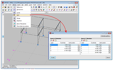
A grid is a mesh composed of lines parallel to the global x and y axes. These lines define a spatial division of the structure in its elevation. Users can assign a name to each gridline and control the position of the name. Gridlines are defined as support for the introduction of structural elements as well as for when defining elevation views (which help when working on the elements of the structure).
This option allows users to introduce, delete or edit Gridlines. A rectangular grid generator has been implemented. If the position of a gridline is modified, all the elements contained on the line will be automatically displaced to the new position.
By default, the grid will always be visible on-screen, unless it is deactivated using the option: “Planes > References”. The grid can also be displayed on drawings. - Views
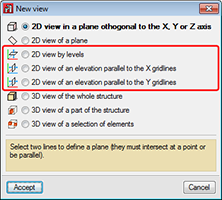
If levels and grids have been defined, the program will allow users to create views for levels and elevations. Once the views have been defined, it is possible to move from one level to the next, or from one elevation to the next, using the

 buttons (up, down, and select levels or elevations) of the scroll bar on the left of the main screen.
Both level views and elevation views are 2D views. Therefore, any element introduced in a view will be contained in that plane. In the case of level views, the program displays elements belonging to the level and those reaching or beginning from it. The program allows for the views to be rotated, so users can better adjust their view of the elements.
The basic version of CYPE 3D (without modules) designs three-dimensional node and bar structures with steel, concrete and generic material sections, and flat shells. Ties working only in tensions can be introduced. The program designs and checks steel sections. Users can upgrade this basic CYPE 3D version by adding any of the CYPE 3D modules to their user license. 
CYPE 3D version limited to the analysis of structures in two dimensions. The same modules as CYPE 3D are optionally available.
CYPE 3D version limited to 50 nodes and 50 bars. No other modules can be added and the design and optimisation of sections is limited to structures containing no more than 10 nodes and 10 bars.
CYPE 3D has a series of modules available which can be acquired separately:
- Footings (includes strap and tie beams)
- Pile caps (includes strap and tie beams)
- Baseplates
- Timber sections
- Joints I. Welded. Warehouses with rolled and welded steel I sections
- Joints II. Bolted. Warehouses with rolled and welded steel I sections
- Joints III. Welded. Building frames with rolled and welded steel I sections
- Joints IV. Bolted. Building frames with rolled and welded steel I sections
- Joints V. Flat trusses with hollow structural sections
- Aluminium and generic sections
- Fire resistance check
- Parallel analysis with two processors
- Parallel analysis with up to eight processors
- Export to Tekla
- Export to TecnoMETAL
- Export in CIS/2 format
There are two reduced versions of CYPE 3D:
CYPE 3D limited to 2 dimensions: CYPE 3D version limited to a two dimensional analysis. The same optional modules are available as those for CYPE 3D.
CYPE 3D student version: CYPE 3D version limited to 50 nodes and 50 bars. It does not include section design or any of the CYPE 3D modules.
Tel. USA (+1) 202 569 8902 // UK (+44) 20 3608 1448 // Spain (+34) 965 922 550 - Fax (+34) 965 124 950