Bars defined as tie-type structural elements
CYPE 3D is an agile and efficient program brought about to carry out structural calculations in three dimensions of bars made of concrete, steel, composite steel and concrete, aluminium, timber or any other material; shells (two-dimensional elements with a constant thickness whose perimeter is defined by a polygon). It includes the design of joints (welded and bolted rolled and welded steel I -sections and hollow sections) and of foundations (pad footings, pile caps and baseplates).
This webpage explains bars defined as tie-type structural elements.
For information on other properties of CYPE 3D, visit the CYPE 3D webpage.
Bar structure types in CYPE 3D
CYPE 3D allows users to introduce bars made of concrete, steel, composite steel and concrete, aluminium, timber or any other material.
The program designs the section and provides its optimum size for bars composed of steel, aluminium, timber or concrete (if they have been defined as column or beam-type structural elements).
Composite steel and concrete bars can be defined if they have been introduced as column-type structural elements and, even though they are not designed automatically, they are checked by the program with the properties that have been indicated by users.
As of the 2016.a version, users are required to define the structural function an element carries out in CYPE 3D. There are 4 different structural types available: Generic-type structural elements, Tie-type structural elements, Column-type structural elements and Beam-type structural elements.
This webpage describes bars defined as column-type structural elements. To consult the properties of bars defined as other types of structural elements, please consult the following links: Generic-type structural elements , Column-type structural elements and Beam-type structural elements.
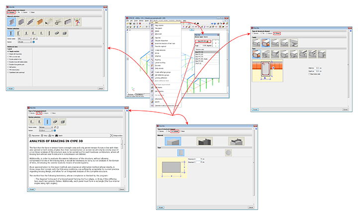
CYPE 3D allows users to design ties defined as having a flat bar, angle, solid round bar or solid square bar section.
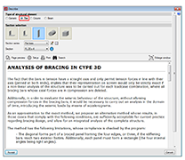
In the Describe dialogue box, users can select the Tie-type structural element. Once selected, a text appears explaining the analysis method used and conditions applied for its design.
Since ties are straight bars which only work in tension in the direction of their axis, their use in the model would only be exact if a non-linear analysis of the structure were to be carried out for each loadcase combination, and remove, for each analysis, all ties whose axial forces are in compression.
Furthermore, to carry out a dynamic analysis without taking into account the ties in compression, an analysis would have to be performed in the time domain with accelerograms.
As an approximation to the exact method, we propose an alternative method whose results, for cases which meet the conditions detailed below, are sufficiently acceptable for the design of structures with Tie-type structural elements.
The method has the following conditions, which the program ensures are met:
- The “Tie” element forms part of a rigid bracing system framed at its four sides, or three of its sides if the bracing reaches external fixities. Additionally, each rigid frame must form a rectangle (four internal angles must be right angles).
- The axial stiffness of the ties (AE/L) is less than 20% of the axial stiffness of the elements framing the bracing elements.
- The diagonal ties of a frame must both have the same section.
More information on the analysis method applied by the program for the design of ties can be found in the CYPE 3D calculations manual or in the Describe dialogue box (which opens when a bar is described as a tie).
The basic version of CYPE 3D (without modules) designs three-dimensional node and bar structures with steel, concrete and generic material sections, and flat shells. Ties working only in tensions can be introduced. The program designs and checks steel sections. Users can upgrade this basic CYPE 3D version by adding any of the CYPE 3D modules to their user license. 
CYPE 3D version limited to the analysis of structures in two dimensions. The same modules as CYPE 3D are optionally available.
CYPE 3D version limited to 50 nodes and 50 bars. No other modules can be added and the design and optimisation of sections is limited to structures containing no more than 10 nodes and 10 bars.
CYPE 3D has a series of modules available which can be acquired separately:
- Footings (includes strap and tie beams)
- Pile caps (includes strap and tie beams)
- Baseplates
- Timber sections
- Joints I. Welded. Warehouses with rolled and welded steel I sections
- Joints II. Bolted. Warehouses with rolled and welded steel I sections
- Joints III. Welded. Building frames with rolled and welded steel I sections
- Joints IV. Bolted. Building frames with rolled and welded steel I sections
- Joints V. Flat trusses with hollow structural sections
- Aluminium and generic sections
- Fire resistance check
- Parallel analysis with two processors
- Parallel analysis with up to eight processors
- Export to Tekla
- Export to TecnoMETAL
- Export in CIS/2 format
There are two reduced versions of CYPE 3D:
CYPE 3D limited to 2 dimensions: CYPE 3D version limited to a two dimensional analysis. The same optional modules are available as those for CYPE 3D.
CYPE 3D student version: CYPE 3D version limited to 50 nodes and 50 bars. It does not include section design or any of the CYPE 3D modules.
Tel. USA (+1) 202 569 8902 // UK (+44) 20 3608 1448 // Spain (+34) 965 922 550 - Fax (+34) 965 124 950