
Bars defined as generic-type structural elements
CYPE 3D is an agile and efficient program brought about to carry out structural calculations in three dimensions of bars made of concrete, steel, composite steel and concrete, aluminium, timber or any other material; shells (two-dimensional elements with a constant thickness whose perimeter is defined by a polygon). It includes the design of joints (welded and bolted rolled and welded steel I -sections and hollow sections) and of foundations (pad footings, pile caps and baseplates).
This webpage explains bars defined as column-type structural elements.
For information on other properties of CYPE 3D, visit the CYPE 3D webpage.
Bar structure types in CYPE 3D
CYPE 3D allows users to introduce bars made of concrete, steel, composite steel and concrete, aluminium, timber or any other material.
The program designs the section and provides its optimum size for bars composed of steel, aluminium, timber or concrete (if they have been defined as column or beam-type structural elements).
Composite steel and concrete bars can be defined if they have been introduced as column-type structural elements and, even though they are not designed automatically, they are checked by the program with the properties that have been indicated by users.
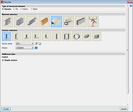
As of the 2016.a version, users are required to define the structural function an element carries out in CYPE 3D. There are 4 different structural types available: Generic-type structural elements, Tie-type structural elements, Column-type structural elements and Beam-type structural elements.
This webpage describes bars defined as column-type structural elements. To consult the properties of bars defined as other types of structural elements, please consult the following links: Tie-type structural elements , Column-type structural elements and Beam-type structural elements.
Generic-type structural elements
Elements defined this way do not have a specific structural role in the program. They can be defined as made of:
- Steel (rolled, welded or cold-formed)

- Aluminium
- Timber
- Reinforced concrete
- Any other user-defined material
The program designs the bars automatically if they have been defined as made of rolled, welded or cold-formed steel; aluminium or timber.
If they have been defined as reinforced concrete bars or bars made of a user-defined generic material, the program calculates the forces to which they are exposed and displays the results by simple loadcase, combination or envelopes; but their sections are neither checked nor designed. To check and design reinforced concrete bars in CYPE 3D, they must be defined as Column-type or Beam-type structural elements.
For steel bars, the program uses rolled, cold-formed and welded steel sections managed from its vast database made up of a large variety of sections available from main manufacturers and section tables. Composite sections can be created based on simple sections using a welded connection, batten plates, lateral plates, etc…Haunches at bar ends; variable section bars; steel castellated beams with hexagonal, octagonal or circular openings; and steel sections with a concrete slab can be defined. The program carries out a fire resistance check and designs the protective coating for steel sections.
Using the Aluminium and generic sections module of CYPE 3D and Integrated 3D structures of CYPECAD, extruded aluminium bars of the alloys and tempers described in the Alloys and Tempers section, with the geometry indicated in Aluminium sections can be analysed and designed in accordance with Eurocode 9 EN 1999-1-1.
Within the Describe section dialogue box (Bar > Describe section), the aluminium section button is available which allows users to assign an aluminium section to a bar, from the section library included with the program or to define it geometrically.
The library contains a series of official sections which the user can configure. The range of sections available in the library and created by the user include:
- I-sections
- Channels
- Batten plates
- T-sections
- Angle
- Symmetrical angle
- Rectangular tube
- Circular hollow section
- Round bar
- Square bar
An extruded aluminium section editor was implemented in the 2011.a version of the program, whose purpose is to aid users in defining their own transverse aluminium section designs. More information on the use of this type of sections can be found within the Special extruded aluminium sections explanation in the New features of the 2011 version of CYPE 3D and Integrated 3D structures.
In the 2012.a version, improvements were also implemented regarding the automatic calculation of the susceptibility to local buckling due to compression and in the design of special aluminium sections. More information can be found in the New features for aluminium sections article in the New features of the 2012 version in CYPE 3D and Integrated 3D structures webpage.
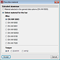
Within the Describe material dialogue box (Bar > Describe material) the alloy of the extruded aluminium for the selected aluminium sections is chosen, as well as it temper. The available alloys with their corresponding tempers are:
| Aluminium alloy | Temper |
| EN AW-5083 | F, H111 and H112 |
| EN AW-6060 | T5, T6, T64 and T66 |
| EN AW-6061 | T4 and T6 |
| EN AW-6063 | T5, T6 and T66 |
| EN AW-6005A | T6 |
| EN AW-6106 | T6 |
| EN AW-6082 | T4, T5 and T6 |
| EN AW-7020 | T6 |
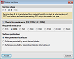
Using the Timber sections module, CYPE 3D desings sawn wood (conifer and poplar species), sawn wood (frondescent species), homogenous glue laminated wood and combined glue laminated wood sections. Sections that can be defined include rectangular, with constant or variable section, and round sections. It includes a library of timber sections that users can configure and extend. The program also carries out a fire resistance check of the timber sections so they comply with the selected code, if the user activates the fire resistance check of timber sections.
Concrete bars (defined as generic-type structural elements)
Rectangular or round concrete bars with constant depth can be introduced in the program as well as rectangular concrete bars with variable depth. The program calculates the forces to which these bars are submitted to and displays the results for each simple loadcase, combination or envelope. The program does not carry out a resistance check of the concrete bars, i.e., the bars are neither checked nor are their sections designed. To check and design reinforced concrete bars in CYPE 3D, they must be defined as Column-type or Beam-type structural elements.
CYPE 3D allows users to define generic bars composed of any material. The program calculates the forces to which these bars are exposed to and displays the results for each simple loadcase. The program does not carry out a resistance check of the generic bars, i.e., the bars are neither checked nor are their sections designed. Users have to define the following properties of the bars once they have been positioned within the structure:
- Geometry of the section
The distances between the centre of gravity and the outer perimeter of the section measured in the four directions of the two main local axes of the section:- Left width
- Right width
- Bottom depth
- Top depth
- Mechanical properties
- Area
- Shear area Avy
- Shear area Avz
- Bending inertia Iyy
- Bending inertia Izz
- Torsional inertia It
- Top depth
- Mechanical properties
- Area
- Shear area Avy
- Shear area Avz
- Material properties
- Modulus of elasticity
- Poisson’s ratio
- Thermal expansion coefficient
- Unit weight
The basic version of CYPE 3D (without modules) designs three-dimensional node and bar structures with steel, concrete and generic material sections, and flat shells. Ties working only in tensions can be introduced. The program designs and checks steel sections. Users can upgrade this basic CYPE 3D version by adding any of the CYPE 3D modules to their user license.
CYPE 3D version limited to the analysis of structures in two dimensions. The same modules as CYPE 3D are optionally available.
CYPE 3D version limited to 50 nodes and 50 bars. No other modules can be added and the design and optimisation of sections is limited to structures containing no more than 10 nodes and 10 bars.
CYPE 3D has a series of modules available which can be acquired separately:
- Footings (includes strap and tie beams)
- Pile caps (includes strap and tie beams)
- Baseplates
- Timber sections
- Joints I. Welded. Warehouses with rolled and welded steel I sections
- Joints II. Bolted. Warehouses with rolled and welded steel I sections
- Joints III. Welded. Building frames with rolled and welded steel I sections
- Joints IV. Bolted. Building frames with rolled and welded steel I sections
- Joints V. Flat trusses with hollow structural sections
- Aluminium and generic sections
- Fire resistance check
- Parallel analysis with two processors
- Parallel analysis with up to eight processors
- Export to Tekla
- Export to TecnoMETAL
- Export in CIS/2 format
There are two reduced versions of CYPE 3D:
CYPE 3D limited to 2 dimensions: CYPE 3D version limited to a two dimensional analysis. The same optional modules are available as those for CYPE 3D.
CYPE 3D student version: CYPE 3D version limited to 50 nodes and 50 bars. It does not include section design or any of the CYPE 3D modules.
Tel. USA (+1) 202 569 8902 // UK (+44) 20 3608 1448 // Spain (+34) 965 922 550 - Fax (+34) 965 124 950