


Using the “Composite steel and concrete columns”, CYPECAD and CYPE 3D design composite steel and concrete columns composed of rectangular or circular concrete columns with an encased steel section, Rolled steel plate box sections, filled with concrete; rectangular, square and circular hollow sections filled with concrete.
Using the “Composite steel and concrete columns” module, CYPECAD and CYPE 3D can check composite steel and concrete columns composed of a rectangular or circular concrete section with an encased section; rolled steel plate box sections, filled with concrete; and cold-formed steel rectangular, square or circular hollow sections, filled with concrete. 
CYPECAD and CYPE 3D also design reinforced concrete columns using the Concrete columns module and steel columns (only CYPECAD requires the Steel columns module).
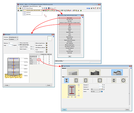
CYPECAD allows users to define, for each column that is introduced, specific values for the following parameters during its introduction (whose values are defined in the general data of the job or in the analysis options):
- Effective length factors
- Fixity coefficients at the top and bottom of each column span
- Axial stiffness coefficients
- Cover
- Concrete resistance
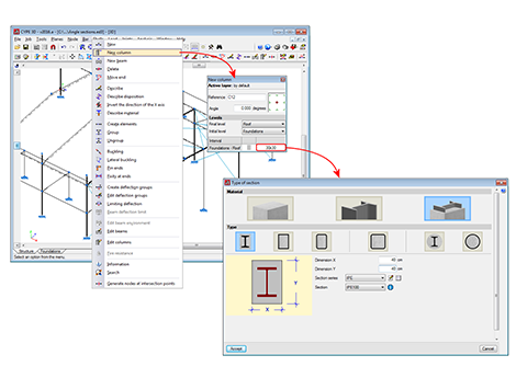
In CYPE 3D, these properties are defined using different options in the Bar menu.
In CYPECAD, when introducing the data, the fixed point of the columns can be defined (at corners or faces) for when the section size of a column varies from one floor to another. In CYPE 3D, the fixed point is defined using the “Describe disposition” option in the “Bar” menu.
Columns introduced in CYPECAD and in CYPE 3D must be vertical. CYPECAD does not allow for them to be introduced any other way, however in CYPE 3D, users could define a bar, as being a column-type structural element, whose local X-axis is at an angle with respect to the global Z-axis. In these cases, CYPE 3D marks the bar as containing an error (if the “Show/Hide incidents” option in the “Analysis” menu has been activated) with the following message: “The element must be vertical, with its local X-axis in the ascending direction”. The program does not allow for the structure to be analysed (and also displays this problem if the analysis is launched regardless of whether the “Show/Hide incidents” option has been activated or not) until the direction of the local X-axis of the bar does not coincide with that of the global Z-axis.
CYPECAD and CYPE 3D check the following types of composite columns:
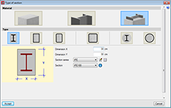
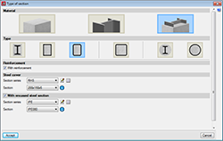
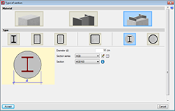
- Rectangular section with encased section
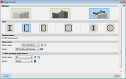
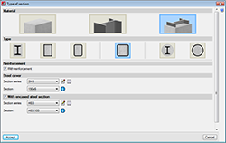
Always includes longitudinal and transverse reinforcement - Rolled steel plate box section, filled with concrete
It is possible to include longitudinal and transverse reinforcement, and an encased steel section. - Cold-formed steel rectangular hollow section, filled with concrete
It is possible to include longitudinal and transverse reinforcement, and an encased steel section. - Cold-formed steel square hollow section, filled with concrete
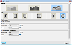
It is possible to include longitudinal and transverse reinforcement, and an encased steel section. - Circular column with encased section
Always includes longitudinal and transverse reinforcement - Cold-formed steel circular hollow section, filled with concrete
It is possible to include longitudinal and transverse reinforcement, and an encased steel section.
CYPECAD and CYPE 3D check the types of columns indicated in the previous section, in accordance with the following codes:
- EN 1994-1-1
Eurocode 4: Design of composite steel and concrete structures – Part 1-1: General rules and rules for buildings. - ANSI/AISC 360-10
Specification for Structural Steel Buildings (ANSI/AISC 360-10).
The code for the design of composite columns is not selected directly as is done with the concrete or steel codes. The program uses either the “EN 1994-1-1” code or the “ANSI/AISC 360-10” code depending on the concrete code that has been selected. Furthermore, bear in mind that CYPECAD and CYPE 3D can only check composite columns when the selected concrete code is implemented in the Advanced column editor.
Concrete code used by “EN 1994-1-1” to check composite columns
The EN 1994-1-1 code will be used by CYPECAD and CYPE 3D to check composite columns when the concrete code is one of the following:
- ABNT NBR 6118:2007 (Brazil)
Norma Brasileira ABNT NBR 6118 (2007). Projeto de estruturas de concreto - Procedimento. - ABNT NBR 6118:2014 (Brazil)
Norma Brasileira ABNT NBR 6118 (2014). Projeto de estruturas de concreto - Procedimento. - BAEL 91 (R-99) (France)
Règles techniques de conception et de calcul des ouvrages et constructions en béton armé suivant la méthode des états limites. - EHE-08 (Spain)
Instrucción de hormigón estructural. - Eurocode 2 (EU)
Design of concrete structures. EN 1992-1-1:2004/AC 2008. - Eurocode 2 (France)
Calcul des structures en béton. NF EN 1992-1-1 :2005/NA: Mars 2007. - Eurocode 2 (Portugal)
Projecto de estruturas de betão. NP EN 1992-1-1:2010/NA. - Eurocode 2 (Rumania)
Eurocode 2: Design of concrete structures. SR EN 1992-1-1:2004/AC. - IS 456: 2000 (India)
Indian Standard. Plain and reinforced concrete code of practice (Fourth Revision). - NTC: 14-01-2008 (Italy)
Norme tecniche per le costruzioni. - SP 63.13330.2012 (Russia)
Concrete and reinforced concrete. Construction. Updated edition SNIP 52-01-2003. Moscow 2012.
Concrete code used by “ANSI/AISC 360-10” to check composite columns
The “ANSI/AISC 360-10” code will be used by CYPECAD and CYPE 3D to check composite columns when the concrete code is one of the following:
- ACI 318M-08 (USA)
Building Code Requirements for Structural Concrete (ACI 318M-08). - ACI 318M-11 (USA)
Building Code Requirements for Structural Concrete (ACI 318M-11). - CIRSOC 201-2005 (Argentina)
Reglamento Argentino de Estructuras de Hormigón. - NCh 430.Of2008 (Chile)
Norma Chilena oficial NCh430.Of2008 (Basada en ACI 318-05). - NSR-10 (Colombia)
Reglamento Colombiano de Construcción Sismo Resistente NSR-10. Título C ¬ Concreto estructural. - NTCRC: 2004 (Mexico)
Normas técnicas complementarias del reglamento de construcciones para el Distrito Federal. - NTE E.060: 2009 (Peru)
Reglamento nacional de edificaciones. Norma E.060 Concreto Armado.
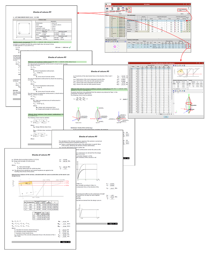
CYPECAD and CYPE 3D have an advanced column editor (for concrete, steel and composite columns), which allows users to:
- Display all the information regarding their design (for composite columns, only their check), and generates detailed reports of the ultimate limit state checks (U.L.S. checks).
- Organise column groups in the column schedule, filter their display, modify the reinforcement or steel sections used, and all this on the columns schedule view and not on-plan. A small plan view diagram is also provided, which allows users to select, in the schedule, the column type to which a specific column belongs to.
- Check all the modifications that are carried out.
- Redesign the columns (except composite and steel columns which can only be checked).
More information on this tool, available for CYPECAD and CYPE 3D, can be found in the “Advanced column editor” webpage.
For CYPECAD or CYPE 3D to be able to design composite steel and concrete columns, users must have the required permits to be able to use either program and the “Composite steel and concrete columns” module (used by both CYPECAD and CYPE 3D).
CYPECAD and CYPE 3D versions and modules
CYPECAD versions
CYPECAD is available in its unlimited version and also in two limited versions called LT30 and LT50, which contain the same tools and module acquisition possibilities, but have the following conditions:
CYPECAD LT50:
- Fifty columns
- Four floor groups (Floor group: floors which are the same and consecutive)
- Total of five floors
- Walls: one hundred linear metres
CYPECAD LT30:
- Thirty columns
- Four floor groups (Floor group: floors which are the same and consecutive)
- Total of five floors
- Walls: one hundred linear metres
Integrated 3D structures of CYPECAD (also LT50 and LT30) is not technically a module. To define these 3D structures in CYPECAD, users must also have the required permits to use CYPE 3D in their user license and, optionally, modules which are exclusive to CYPE 3D.
The following modules are those that can be acquired together with CYPECAD or CYPECAD LT:
- Steel columns
- Steel beams
- Joist floor slabs (generic concrete joists)
- Joist floor slabs (in-situ, precast and steel)
- Timber joist floor slabs
- Waffle slabs
- Flat slabs
- Punching shear verification (Also operates as an independent program)
- Composite slabs
- Hollow core slabs
- Post-tensioned concrete slabs for buildings
- Shear walls
- Reinforced concrete walls
- Plane stress walls
- Stairs
- Mat foundations and foundation beams
- Concrete block walls
- Interaction of the structure with the construction elements
- Automatic job introduction: DXF, DWG and CAD/BIM models
- Collective protection systems
Modules common to CYPECAD and CYPE 3D:
- Concrete columns
- Composite steel and concrete columns
- Concrete beams
- Timber sections
- Pile caps (includes strap and tie beams)
- Baseplates
- Footings (pad and strip) (includes strap and tie beams)
- Advanced design of surface foundations
- Fire resistance check
- Parallel analysis with two multiprocessors
- Parallel analysis with up to eight processors
- Joints I. Welded. Warehouses with rolled and welded steel I sections
- Joints II. Bolted. Warehouses with rolled and welded steel I sections
- Joints III. Welded. Building frames with rolled and welded steel I sections
- Joints IV. Bolted. Building frames with rolled and welded steel I sections
- Joints V. Flat trusses with hollow structural sections
- Export to Tekla
Tel. USA (+1) 202 569 8902 // UK (+44) 20 3608 1448 // Spain (+34) 965 922 550 - Fax (+34) 965 124 950